2-wire Transmitters Current Loops Inst Tools . 2-wire (“loop-powered”) transmitter current loops. It is possible to convey electrical power and communicate analog information over the same two wires using 4 to 20 milliamps DC, if we.
2-wire Transmitters Current Loops Inst Tools from qph.fs.quoracdn.net
– The actual wiring between the transmitter and the power supply depends upon whether it is a 2-wire or a 4-wire type. – A 4-wire transmitter has 2 wires connected to a.
Source: e2e.ti.com
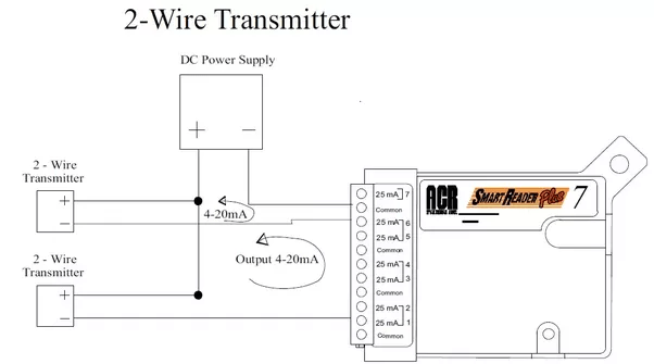
A 2-wire transmitter is loop-powered, which means it is powered by a low voltage, low current, DC power supply, typically 24V. A 4-20mA current is usually supplied by a distributed control.
Source: www.plcacademy.com
Search for jobs related to 2 wire transmitter wiring diagram or hire on the world's largest freelancing marketplace with 20m+ jobs. It's free to sign up and bid on jobs.
Source: 3.bp.blogspot.com
Emerson Global Emerson
Source: 4.bp.blogspot.com
USER INSTRUCTIONS Installation Operation Maintenance attempting to install, operate, or troubleshoot the Limitorque L actuator. 1994 Gmc K1500 5.7 Starter Wiring Diagram.
Source: realpars.com
the current loop. Type 4 refers to a 4-wire transmitter where the Transmitter and Receiver float, and separate power leads power the transmitter outside of the current loop. Four-wire.
Source: realpars.com
A Pressure Transmitter is a 2-part device consisting of a pressure transducer and a circuit that transmits a standard instrumentation signal.. more two-wire transmitters sharing.
Source: control.com
Siemens uses the terminology '4-wire' for powered, active 4-20mA signals. So you need to look at the 4 wire wiring diagram 3-2 in the manual, not the 2-wire wiring diagram 3.
Source: i.ytimg.com
It is a typical usage of two-wire 4-20mA pressure transmitters for most customers showed in figure 1. After the pressure transmitter is powered on, the loop current is proportional to the.
Source: control.com
#analog #senor #PLC #learningPlease Subscribe to Easy PLC Tutorials for more Videos and Tutorialshttps://www.youtube.com/channel/UCJGQuA3wmheCHiTBBBlt8pA?sub...
Source: 4.bp.blogspot.com
Therefore, the first appeared is the four-wire transmitter. That is, the two wires are responsible for the power supply. The outer two wires are responsible for outputting the.
Source: i.ytimg.com
There are three possible ways to connect the Pt100 to the transmitter: in a 2-, 3- or 4-wire connection. Fig.: Pt100 in 2-wire connection. Pt100 in 2-wire connection.. A Pt1000.
Source: control.com
4 Wire RTD. The 4 wire RTD is the most accurate of all RTD configurations. 4 wire RTD not only eliminates the lead wire resistance but also eliminates other resistances added up from the.
Source: i.stack.imgur.com
#PLC #DCS #WIRINGHow to wire two wire transmitter (PT) connection to DCS/PLC using Isolator and to local displayJoin this channel to get access to perks:http...
Source: cdn.instrumentationtools.com
Posted 26 Sep 2017 by Nikolay. 2, 3 and 4 Wire loops. 2, 3 and 4 Wire loops in their vary basics. Description and wiring examples. Two-wire 4-20mA loops (loop powered device)..
Source: res.cloudinary.com
In the case of a 4- wire transmitter, two wires are used for the data signal and two wires for the power supply. This is the simplest form of the 4-20mA measurement loop in.
Source: cdn.instrumentationtools.com
It is possible to convey electrical power and communicate analog information over the same two wires using 4 to 20 milliamps DC, if we design the transmitter to be loop-powered.A loop.
0 komentar